PASSENGER VEHICLES-COMMERCIAL VEHICLES-FLEETS


DND MEMBER & FAMILY DISCOUNTS
- Scheduled Maintenance
- Diesel
- Appraisals
- Charging/Starting System
- Tow Service
- Engines & Transmissions
- Window Motors & Glass
- Auto Sales
- Latches, Springs & Misc
- Air Conditioning/HVAC
- Auto Parts
- Pre-Purchase Inspection
- Exhaust Systems
- Brake Service & Parts
- Electrical Systems
- Steering
- Safety Standards Inspections & Certificates-Motorcycles
- Safety Standards Inspections & Certificates-Passenger Vehicles
- Safety Standards Inspections & Certificates-Trucks/Heavy Duty/Commecial/Trailers
- Tune-ups
- Suspension
- Oil Changes
- Preventative Maintenance
- Differentials/Universal Joints
- Fuel Systems
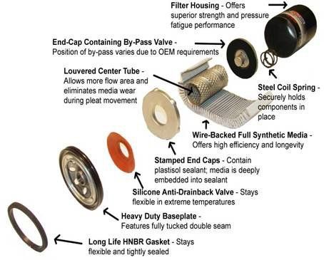
OIL CHANGE
Changing the engine oil helps you save money on gas.
- When the oil gets low or dirty, then friction increases as the engine works harder to create energy. This increased friction burns more fuel. Less friction, less fuel.
- More friction causes higher temperatures which can result in overheating and permanent damage.
- Dirty or low oil and overheating can also wear down and damage other related parts
- For a longer lasting, well functioning vehicle, regular oil checking and changing are one of the most important services to maintain faithfully.
BODY PARTS


We are not a body shop and do not paint, however we do replace most changeable items such as headlight casings, mirrors, shrouds, door handles, door and trunk latches, wiper linkage, etc.
BRAKE SYSTEMS
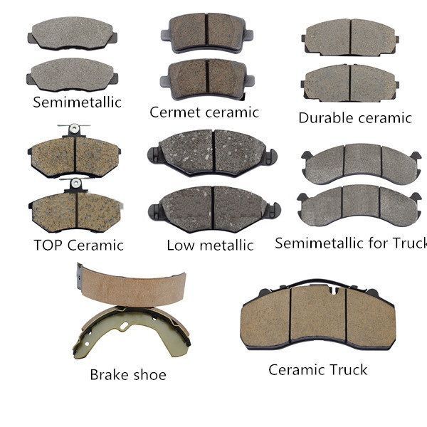
ORGANIC BRAKE PADS
Originally, brake pads were made from asbestos, a heat-absorbing material that was well-suited for the wear and tear that brake pads took on. However, asbestos has been found to be a highly-potent carcinogen and prolonged exposure to it can cause cancer. Asbestos-based brake pads would wear down over time, releasing asbestos that stuck to tires and get into the air. Manufacturers realized asbestos wasn’t a safe compound to use for manufacturing braking systems. As a result, organic brake pads, or non-asbestos organic (NAO) brake pads, were created to fill the gap.
Organic brake pads are made of a mixture of fibers and materials such as rubber, carbon compounds, glass or fiberglass, Kevlar, and more, and are bound together with resin. They tend to produce less dust than some other types of brake pads, such as metallic ones, and are available at a reasonably low price point. Unlike performance brake pads, which are primarily used in heavy and high-performance vehicles, organic brake pads generate a moderate amount of friction without much heat being present, making them suitable for drivers who use their cars for normal driving and commuting. Organic brake pads also tend to be quiet and don’t put much stress on the brake rotors.
However, organic brake pads do have some disadvantages when compared to other types of brake pads. Because of their composite nature, organic brake pads can tend to wear out a bit more quickly, meaning they might have to be replaced more often. They also tend to function best within a smaller range of temperatures, meaning they don’t work as well in extreme weather or when they are being pushed too hard and overheat. Organic brake pads also have a higher level of compressibility, which means the driver has to press the brake down with more force to engage them.
CERAMIC BRAKE PADS
Another option for brake pads are ceramic brake pads. These brake pads are made from ceramic very similar to the type of ceramic used to make pottery and plates, but is denser and a lot more durable. Ceramic brake pads also have fine copper fibers embedded within them, to help increase their friction and heat conductivity.
Since they were developed in the mid-1980s, ceramic brake pads have been consistently increasing in popularity for a number reasons:
- Noise-Level: Ceramic brake pads are very quiet, creating little-to-no extra sound when the brakes are applied.
- Wear & Tear Residue: Compared to organic brake pads, ceramic brake pads tend to produce less dust and other particles over time as they wear down.
- Temperature & Driving Conditions: Compared to organic brake pads, ceramic brake pads can be more reliable in a wider range of temperatures and driving conditions.
Due to higher manufacturing costs, ceramic brake pads tend to be the most expensive of all types of brake pad. Also, since both ceramic and copper can’t absorb as much heat as other types of materials, more of the heat generated by braking will pass through the brake pads and into the rest of the braking system. This can cause more wear and tear on other braking components. Ceramic brake pads aren’t considered the best choice for extreme driving conditions, such as very cold climates or racing conditions.
METALLIC BRAKE PADS
Metallic brake pads are comprised of anywhere between 30% and 70% metals including copper, iron, steel, or other composite alloys. These various metals are combined with graphite lubricant as well as other fillers to complete the brake bad. The metallic brake pad compounds that are available vary, with each offering their own advantages for different situations as diverse as daily commutes to track racing.
For many drivers, especially those who value high-performance, the choice between ceramic vs. metallic brake pads is easy. Performance-driven drivers prefer the metallic brake pads because they offer improved braking performance in a much wider range of temperatures and conditions. Because metals are such a good conductor of heat, they tend to be able to withstand more heat while simultaneously helping braking systems cool back down more quickly. They also don’t compress as much as organic brakes, meaning less pressure needs to be applied to the brake pedal to affect stopping ability.
However, there are some disadvantages to metallic brake pads. They tend to be noisier than ceramic or organic brake pads - meaning a louder ride - as well as more stressful for the brake system, adding more strain and wear on the brake rotors. As far as price goes, metallic brake pads tend to fall somewhere between organic and ceramic pads. They tend to produce more brake dust than the other two varieties as well.
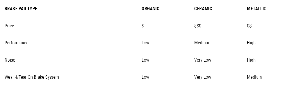
CHOOSING THE CORRECT BRAKE PAD
So which brake pad is the best choice for you when deciding between ceramic brake pads vs semi metallic vs. organic? It really is dependent on the ride you expect from your vehicle combined with your personal driving style. If you have a high-performance sport car, or at least drive your vehicle like it is one, you’re likely best off choosing semi-metallic brake pads. On the other hand, if you do a lot of urban commuting, you might find a solid ceramic brake pad to be the better option. If you don’t put a lot of mileage on your vehicle, an organic brake pad might be the best, low-price option for your driving habits.
Below is a simple table that illustrates some of the comparative differences between organic, ceramic, and metallic brake pads.-https://www.bridgestonetire.com/tread-and-trend/drivers-ed/ceramic-vs-metallic-brake-pads


Solid brake rotors/discs-designed typically for the rear brake system and are machined from a single piece of raw material, like cast iron.
Vented brake rotors/discs-thicker CNC-machined cast-iron discs that have a hollow vent or channel between the front and rear rotor surfaces. This allows for enhanced heat dissipation.
Vented discs usually appear at the front. This configuration helps deal with increased heat/gas dissipation involved with enhanced weight levied by front-engine placement, along with the fact that most cars are brake-biased toward the front, usually on the basis of a 60/40 brake-balance ratio.
Drilled and Slotted rotors/discs-Slotted rotors do not improve heat transfer but instead improve brake output by removing gas and dust that is trapped between the pad and rotor. This gas and dust reduces the friction force by preventing the pad from fully contacting the rotor.
Given the choice between drill holes and slots, the drill holes will give you better braking power over slots for normal city/highway driving. This is why high end BMW, Porsche, Corvette, and Mercedes rotors are drilled, not slotted. However, for track racing (high speed stops), slotted rotors are the better choice.
CHARGING/STARTING SYSTEM
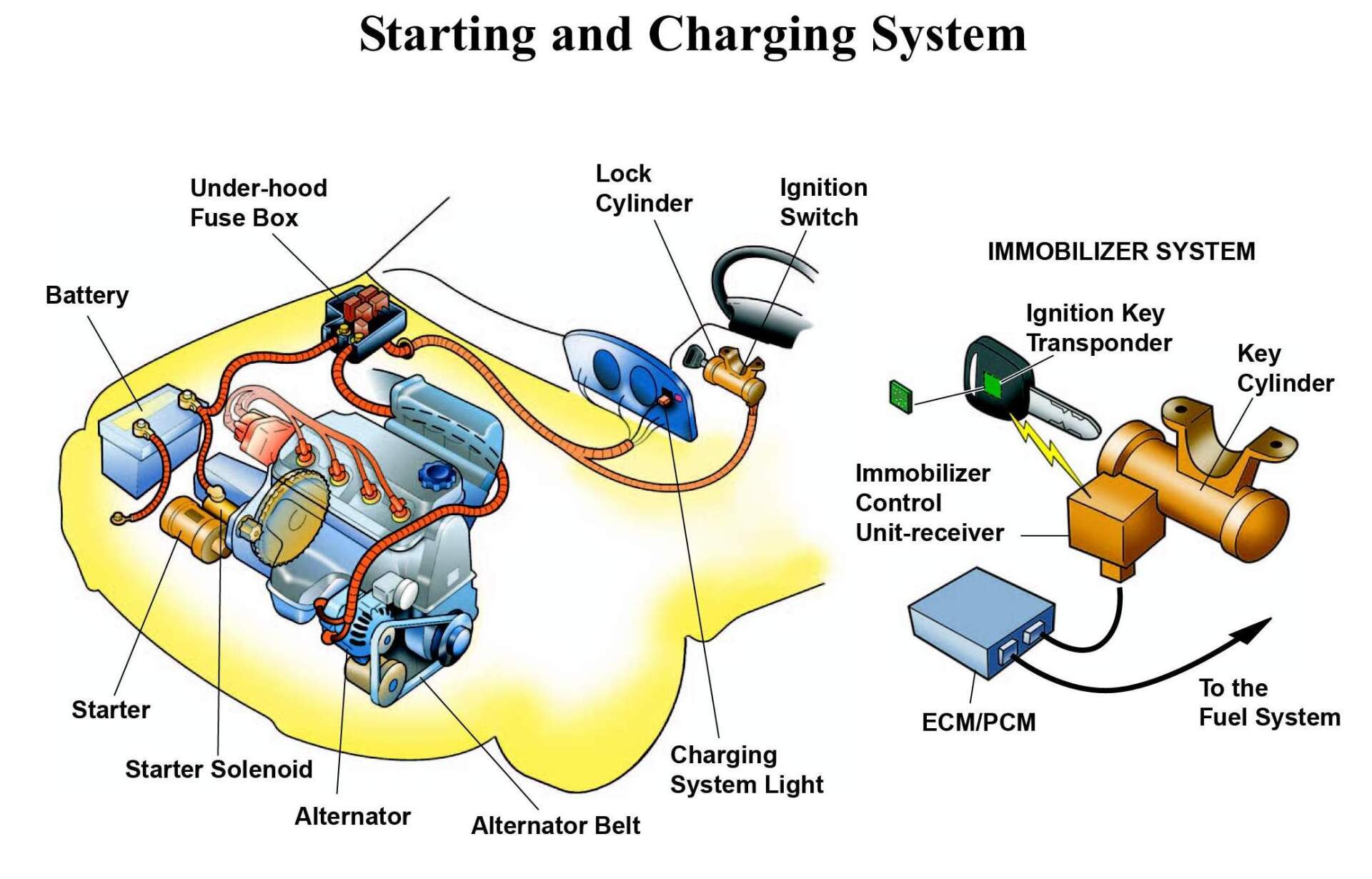
HOW VEHICLE STARTING AND CHARGING WORKS
1
THE BATTERY SUPPLIES POWER TO YOUR VEHICLE
The starting battery converts chemical energy into electrical energy. The three essential parts for this conversion are the anode, the cathode, and the electrolyte.
- The anode is the negatively-charged side of the battery
- The cathode is the positively-charged side
- The electrolyte is a buffer that separates the anode and cathode
Chemical reactions inside of the battery cause electrons to build up in the anode. Like with magnets, the similarly charged particles repel one another, but in a battery the electrolyte blocks these particles from merely switching sides by moving over to the opposite side.
If your battery is more than 4 years old, you should get it tested so you won’t be caught off-guard by a dead battery.
2
BATTERY CABLES AND TERMINALS CARRY CURRENT FROM THE BATTERY
Battery cables connect the battery’s terminals to the vehicle. One end of each cable is connected to either the negative or positive terminal.
- The other end of the negative cable is often connected to the engine or somewhere on the vehicle’s frame
- The positive cable’s other end is typically connected to the starter or a fuse box
Because the electrolyte keeps the charged particles from crossing the battery, electrical current moves from the battery, through the cables, and into the vehicle.
Corrosion and loose connections can keep your cables from working the way they should. Be sure to inspect your cables for looseness or corrosion from time to time. If you have a problem, it’s easy to tighten the cables or to remove corrosion with a wire brush.
3
RELAYS, FUSES, AND THE STARTER RECEIVE ELECTRICAL CURRENT
The moment you turn the key to start in your car (or push the button) a signal is sent to a relay, or series of relays. The main relay in this group is referred to as the starter solenoid. The signal, coming from the ignition, is low amperage. When it hits these relays, and the starter solenoid, this engages a high-amperage current which directly engages the starter.
Your vehicle’s relays and fuses regulate current in the electrical systems.
- A relay is basically a switch that allows small currents to control accessories that would require heavy switches and wiring. Relays reduce the amount of wiring needed by having larger contact areas that can handle large amounts of current. The starter solenoid is generally one of the largest relays in your car because it handles such a huge amperage amount.
- Many vehicles have fuses in-line in their ignition system as well or a main battery or system fuse. These are often seen mounted either directly on the battery cable, or nearby in the engine’s fuse/relay compartment.
- Fuses protect your vehicle’s electronic devices and wiring. If something like, say, your radio tries to draw too much current, the radio’s fuse will blow, cutting off the current’s path to the radio. This prevents the excess current from damaging the radio or melting wires in the system.
After reaching the relays and fuses, current continues to the vehicle’s various electrical systems.
4
THE STARTER TURNS THE ENGINE
When the starter solenoid engages, the starter’s gear, or “bendix” moves out to engage the flywheel or flexplate of the engine, turning it over. The turning of the engine allows the fuel air-mixture to enter into the engine cylinders for combustion, starting the engine.
A clicking noise when you turn the key is a good indicator of low battery voltage that is sufficient enough to engage the relays, but not enough to turn the motor. Often times, you will hear a buzzing sound. This sound is your starter solenoid not fully engaging because of low or insufficient voltage. Or, in some cases, a click indicates that your starter has gone bad. In these cases, a visual inspection and/or removal and bench testing is needed. If the starter is soaked with oil contamination and requires replacement, be sure the oil leak is repaired to prevent damage to the replacement starter.
5
THE ACCESSORY BELT OR SERPENTINE BELT DRIVES THE ALTERNATOR
Once the engine is turning, rotational force from the crankshaft turns the belt pulley. The belt transfers this rotational force to other systems, like the power steering pump, the water pump, and most importantly for this article: the alternator.
6
THE ALTERNATOR RECHARGES THE BATTERY
The alternator is responsible for 2 things at the same time. It supplies voltage power to everything your car uses while it is running. While doing this, it also sends charge to the battery to maintain its charge as well, and in doing so, the battery acts as a capacitor. An alternator works no different than a windmill or turbine, generating AC power, which is then converted to DC power inside the alternator. The 3 items responsible for this inside the alternator are the rotor, stator, and rectifier. The alternator works similarly, except it is turned by the belt rather than a hand or the wind. The two components responsible for generating electricity are the rotor and the stator:
- The rotor features magnetized finger poles that rotate surrounding the wire field winding. Each finger pole is a different length to produce alternating north and south poles for the winding.
- The stator is just enough larger that the rotor can spin without touching the stator walls.
- A rectifier is in a sense a valve. It converts AC power (Alternating Current) into DC power (direct current).
The spinning magnetized poles generate current in the winding, and this current provides the power that charges your battery. Inside your alternator, a voltage regulator makes sure that this voltage is maintained at a proper level for your car’s electrical system. This is usually somewhere between 14-16 volts.
Test your alternator using an alternator/battery tester or voltmeter (Learn how to test an alternator here). Ensure the drive belt is in good condition and does not slip on the alternator pulley. A dead battery, one that won’t stay charged, or headlamps and interior lights that appear dim can indicate that your alternator is possibly bad. Visually inspect your alternator for signs of the problem. If the alternator is replaced, be sure the battery is fully charged before starting the engine. This will prevent overload and potential damage to the replacement alternator. If the drive belt shows signs of wear, replace it to ensure the alternator will perform properly. If equipped with an automatic belt tensioner, inspect it for wear and binding/sticking. If it does not move smoothly it should be replaced along with the belt.- https://www.autozone.com/diy/electrical/rotating-electrical-systems
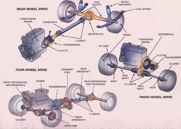
DRIVETRAIN
Most modern automatic gearboxes have a set of gears called a planetary or epicyclic gear train.
A planetary gear set consists of a central gear called the sun gear , an outer ring with internal gear teeth (also known as the annulus, or ring gear ), and two or three gears known as planet gears that rotate between the sun and ring gears.
The drive train is coupled to a mechanism known as a torque converter , which acts as a fluid drive between the engine and transmission .
If the sun gear is locked and the planets driven by the planet carrier , the output is taken from the ring gear, achieving a speed increase.
If the ring gear is locked and the sun gear is driven, the planet gears transmit drive through the planet carrier and speed is reduced.
With power input going to the sun gear and with the planet carrier locked, the ring gear is driven, but transmits drive in reverse.
To achieve direct drive without change of speed or direction of rotation, the sun is locked to the ring gear and the whole unit turns as one.
How a torque convertor works
At high revs the reactor starts to turn. When turbine, impeller and reactor are running at the same speed, oil is not deflected.
At low revs the reactor is stationary and deflects the oil back to the impeller. This increases the torque applied to the turbine.
A torque converter is a fluid coupling that acts like a clutch , except that drive is by hydraulic pressure .
The converter has three main components - the impeller , bolted to the flywheel ; the turbine, connected to the gearbox input shaft ; and the central reactor between the two, which has a one-way clutch called a freewheel.
As the engine speed is increased, the centrifugal force acting on the hydraulic fluid via the impeller vanes transmits the torque, or turning effort, to the turbine.
The central reactor converts this turning effort by redirecting the flow of fluid back to the impeller to give higher torque at low speeds.
Once the engine speeds up and develops more power, the need for this torque amplification decreases and the reactor freewheels. The torque converter then acts as a fluid flywheel, connecting engine to gearbox.
The main components of a torque converter are shown in the diagram - the impeller, reactor (or stator ) and turbine.
The smaller diagrams show the direction taken by the hydraulic fluid under centrifugal forces .
The same effect can also be achieved by locking the planet gears to the planet carrier.
Most automatic gearboxes have three forward speeds, and use two sets of epicyclic gears.
The locking sequences of the epicyclic gear train are achieved by hydraulic pressure operating brake bands or multi-plate clutches.
The bands are tightened round the ring gear to prevent it turning, and the clutches are used to lock the sun gear and planets.
The correct sequence of pressure build-up and release is controlled by a complex arrangement of hydraulic valves in conjunction with sensors that respond to engine load, road speed and throttle opening.
A mechanism linked to the throttle - known as a kickdown - is used to effect a change-down for rapid acceleration. When you press down the accelerator suddenly to its full extent, a lower gear is selected almost instantly.
Most automatic gearboxes have an override system so that the driver can hold a low gear as required.-https://www.howacarworks.com/basics/how-automatic-gearboxes-work
ENGINE
The engine is the heart of your car. It is a complex machine built to convert heat from burning gas into the force that turns the road wheels.
The chain of reactions which achieve that objective is set in motion by a spark , which ignites a mixture of petrol vapour and compressed air inside a momentarily sealed cylinder and causes it to burn rapidly. That is why the machine is called an internal combustion engine . As the mixture burns it expands, providing power to drive the car.
To withstand its heavy workload, the engine must be a robust structure. It consists of two basic parts: the lower, heavier section is the cylinder block, a casing for the engine's main moving parts; the detachable upper cover is the cylinder head .
The cylinder head contains valve-controlled passages through which the air and fuel mixture enters the cylinders, and others through which the gases produced by their combustion are expelled.
The block houses the crankshaft , which converts the reciprocating motion of the pistons into rotary motion at the crankshaft. Often the block also houses the camshaft , which operates mechanisms that open and close the valves in the cylinder head. Sometimes the camshaft is in the head or mounted above it.
Different engine layouts
In-line engine
The simplest and most common type of engine comprises four vertical cylinders close together in a row. This is known as an in-line engine . Cars with capacities exceeding 2,000cc often have six cylinders in line.
V-8 engine
The more compact V-engine is fitted in some cars, especially vehicles with eight or 12 cylinders, and also some with six cylinders. Here the cylinders are arranged opposite each other at an angle of up to 90 degrees.
Horizontally-opposed engine
Some engines have horizontally opposed cylinders . They are an extension of the V-engine, the angle having been widened to 180 degrees. The advantages lie in saving height and also in certain aspects of balance.
The cylinders in which the pistons operate are cast into the block, as are mountings for ancillary equipment such as a filter for the oil which lubricates the engine, and a pump for the fuel. An oil reservoir , called the sump , is bolted underneath the crankcase .-https://www.howacarworks.com/basics/the-engine
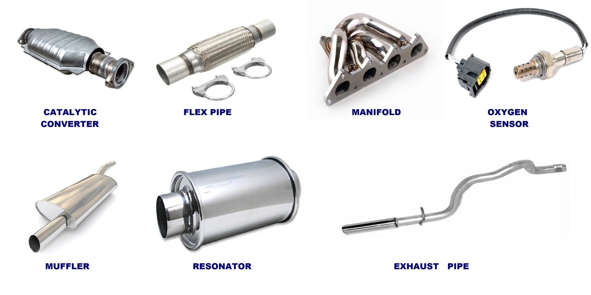
EXHAUST SYSTEM
When your car is running, there are thousands of small explosions inside your engine every minute. Each one produces power by pushing against the engine’s pistons. But the explosions also produce leftover gases. They’re made up of potentially dangerous chemicals such as carbon dioxide, carbon monoxide, hydrocarbons and nitrogen oxides. These gases need to be routed away from the engine compartment so they don’t get into the cabin, and then into your lungs. That’s the basic job of a car’s exhaust system.
In modern-day vehicles, exhaust systems play other roles, too. Just letting those exhaust gases go straight into the atmosphere only means that more people can be affected by them. Further, all the constant engine explosions produce something else that can harm people: noise pollution.
Today’s exhaust systems have parts that are designed to deal with all of those issues.
What is an Exhaust Manifold?
For most cars, it all starts with the exhaust manifold. This is made of metal, usually cast iron, and connects the engine to the rest of the exhaust system. On one side of the manifold are individual tubes that connect to each of the engine cylinders. They merge together in the manifold and come out of the other side in a single tube. (Engines also have intake manifolds that go the other way. Here, a single source of fresh air is split into the separate tubes. The tubes then split off the manifold to take that air to the individual cylinders for combustion.)
What are Headers?
If you’re a hot-rod enthusiast, you may opt for “headers” instead of a traditional exhaust manifold. Headers also collect the exhaust gases from the different cylinders into one tube, but the individual tubes for headers are much longer. This reduces the pressure needed to force the exhaust gases through the system, increasing performance.
What Does an Oxygen Sensor Do?
An oxygen sensor is a part of the exhaust system that helps fine-tune the intake process. Often located in the exhaust manifold, the sensor measures how much oxygen is in the waste gases. In a perfect world, there wouldn’t be any. The engine would use exactly the right amount of oxygen needed to completely burn the fuel, and none of either would be left over. With a modern fuel-injected car, the ECU (engine control unit) analyzes the oxygen reading from the exhaust sensor. The ECU then can help ensure the optimum mixture of air to fuel in the engine cylinder by changing how much fuel is injected.
What is a Catalytic Converter?
The next major component for a mainstream exhaust system is the catalytic converter. It’s connected to the single pipe of exhaust gases collected from the separate cylinders. The catalytic converter “cleans up” three of the less common, but more dangerous, exhaust waste products. Most of what’s produced by the combustion process is nitrogen gas, carbon dioxide and water vapor. But there also are smaller amounts of nitrogen oxides, carbon monoxide and hydrocarbons.
In a catalytic converter, that stuff undergoes a chemical reaction as it comes into contact with certain rare elements. Those elements, or “catalysts,” do two things. First, they break the nitrogen oxides into nitrogen and oxygen. The latter element is then used by a second set of catalysts to “oxidize” the hydrocarbons and carbon monoxide. It’s a way of chemically burning off material that wasn’t combusted in the engine. Without getting deeper into the science, the bottom line is reduced emissions.
Learn More About Catalytic Converters
What Does a Muffler Do?
Waste gases aren’t the only things traveling through your exhaust system. So are sound waves. And it turns out that excessive noise has become a public health issue, even being linked to major heart problems. Mufflers rely on a few main strategies for reducing this noise pollution. One is to route the sound waves through tubes or chambers inside the muffler. The idea is to direct the sound waves so most end up canceling each other out. Additionally, sound-absorbing materials can be packed inside the muffler.
What is an Exhaust Resonator?
Some mufflers are specifically designed to tune the engine sounds to appeal to drivers. For example, part of the aggressive roar of a V8 engine comes from the way its muffler is designed. There also are cars with separate exhaust resonators to take this concept to the next level. Generally located in the exhaust system ahead of the conventional muffler, an exhaust resonator isn’t supposed to reduce the overall volume. Rather, it cancels out only the annoying frequencies and leaves the “good” ones as loud as ever.
What are Exhaust Tips?
At the end of the exhaust system is more hardware connected to the outlet of the muffler. In many cars, that’s a simple straight pipe. You also can add separate exhaust tips to improve the looks, sound and, to some degree, the performance of your vehicle.
What is a Dual Exhaust?
On the topic of exhaust tips, this is a good place to talk about the difference between those and a dual exhaust. Many sporty vehicles will have dual or even quad exhaust tips that are still part of a single exhaust system. That means the only benefits of the extra tips come during the relatively short distance between the muffler and the actual exhaust outlets. A true dual exhaust will have two independent exhaust systems. In a typical V6 or V8 dual exhaust, each bank of cylinders has its own system. As a result, the engine doesn’t have to push the gases from all six or eight cylinders through the same one exhaust pipe into a single muffler. Because the engine wastes less power doing that, there’s more available for performance.
What is a Cat-back Exhaust?
Another term thrown around by enthusiasts is a “cat-back exhaust.” Now, this doesn’t really refer to one specific kind of an exhaust system. It’s more a description of where along the system you’re making changes. If you’ve got a cat-back exhaust, it means you’ve upgraded all parts of your exhaust system behind your catalytic converter. That is, from the “cat” back.
Is a Turbocharger Part of the Exhaust System?
Sort of. You can think of a turbocharger as a single fan with a dual set of blades. They’re like two small wheels separated by a very short axle. One set of the blades is incorporated into the flow of exhaust gas from the engine. The more exhaust gas, the faster these blades spin. Since they’re connected to the other fan blades, those start spinning as well. The second set, however, is part of the intake system. They suck in more fresh air to force into the engine cylinders so they can create more power.
https://www.carfax.com/blog/how-does-an-exhaust-system-work
FUEL SYSTEM
A car engine burns a mixture of petrol and air. Petrol is pumped along a pipe from the tank and mixed with air in the carburettor , from which the engine sucks in the mixture.
In the fuel-injection system, used on some engines, the petrol and air are mixed in the inlet manifold .
A fuel pump draws petrol out of the tank through a pipe to the carburettor .
The pump may be mechanical worked by the engine - or it may be electric, in which case it is usually next to or even inside the fuel tank .
Keeping the petrol tank safe
For safety, the petrol tank is placed at the opposite end of the car from the engine.
Inside the tank, a float works an electrical sender unit that transmits current to the fuel gauge, signalling how much petrol is in the tank.
The tank has an air vent - usually a pipe or a small hole in the filler cap to allow air in as the tank empties. Some of the latest systems have a carbon filter , so that fuel fumes do not escape.
How a mechanical pump works
Mechanical fuel pump
In a mechanical pump the actuating lever moves up and down constantly, but pulls the diaphragm down only as needed to refill the pump chamber. The return spring pushes the diaphragm up to deliver petrol to the carburettor.
A mechanical fuel pump is driven by the camshaft , or by a special shaft driven by the crankshaft . As the shaft turns, a cam passes under a pivoted lever and forces it up at one end.
The other end of the lever, which is linked loosely to a rubber diaphragm forming the floor of a chamber in the pump, goes down and pulls the diaphragm with it.
When the lever pulls the diaphragm down, it creates suction that draws fuel along the fuel pipe into the pump through a one-way valve .
As the revolving cam turns further, so that it no longer presses on the lever, the lever is moved back by a return spring , relaxing its pull on the diaphragm.
The loosely linked lever does not push the diaphragm up, but there is a return spring that pushes against it.
The diaphragm can move up only by expelling petrol from the chamber. The petrol cannot go back through the first one-way valve, so it goes out through another one leading to the carburettor.
The carburettor admits petrol only as it needs it, through the needle valve in its float chamber (See How variable-jet carburettors work ).
While the carburettor is full and the needle valve is closed, no petrol leaves the pump. The diaphragm stays down, and the lever idles up and down.
When the carburettor accepts more petrol, the return spring pushes the diaphragm up and, by taking up the slack in the loose linkage, brings it back into contact with the lever, which again pulls it down to refill the pump chamber.
How an electric pump works
Electric fuel pump
An electric pump has a similar diaphragm mechanism; it is worked by a rod that is drawn into a solenoid switch until it opens a set of contacts to turn off the current.
An electric pump has a similar diaphragm-and-valve arrangement, but instead of the camshaft, a solenoid (an electromagnetic switch ) provides the pull on the diaphragm.
The solenoid attracts an iron rod that pulls the diaphragm down, drawing petrol into the chamber.
At the end of its travel the iron rod forces apart a set of contacts, breaking the current to the electromagnet and relaxing the pull on the diaphragm.
When the diaphragm return spring raises the diaphragm, it also pulls the rod away from the contacts; they then close so that the solenoid pulls the rod and diaphragm down again.
Circulating petrol continuously
Most mechanical and electrical systems pump fuel only when the carburettor needs it. An alternative system has a complete circuit of pipes, from the tank to the carburettor and back again. The pump sends petrol continuously round this circuit, from which the carburettor draws petrol as it needs it.
Filtering petrol and air
Both petrol and air are filtered before passing into the carburettor.
The petrol filter may be a replaceable paper one inside a plastic housing in the fuel line . A pump may include a wire or plastic gauze filter, and sometimes a bowl to catch sediment .
The air cleaner is a box fitted over the carburettor air intake, usually containing a replaceable paper-filter element .-https://www.howacarworks.com/basics/how-a-fuel-pump-works
HVAC SYSTEM

The purpose of the vehicle air conditioning system is to cool the air entering the passenger compartment and remove the moisture from the air so it feels more comfortable in the vehicle. In many vehicles, air conditioning also cycles during the defrost setting, pulling the humidity from the windshield to improve visibility.
The common components of vehicle air conditioning systems are:
-Compressor
-Condenser
-Expansion Valve or Orifice Tube
-Receiver Drier, or Accumulator
-Evaporator
The vehicle air conditioning is pressurized by a gas called a refrigerant. Usually three to four pounds of refrigerant is used to fill the system in most vehicles. The compressor compresses the refrigerant from a gas to a fluid and the fluid is cycled through a refrigerant line. Next the inside the condenser, the refrigerant flow through a small grid and air passes through the condenser removing heat from the refrigerant. Next the refrigerant moves on to the expansion valve or orifice tube where the pressure in the line is reduced and the refrigerant is returned to a gaseous state.
The refrigerant then enters the receiver drier, or accumulator, which removes moisture from that is carried in with the refrigerant in gas form. After which the drier, cooler refrigerant passes to the evaporator still in gas form. Air is blown through the evaporator core, the heat is removed from the air and transferred into the refrigerant, leaving cooler air to blow into the passenger compartment. The refrigerant cycles through the compressor again and the cycle continues.-https://medium.com/@caknowapp/how-it-works-vehicle-air-conditioning-systems-d6d5ef704c33
FUSES
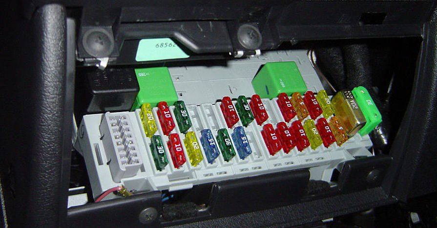
A fuse is a mechanical breaker device that protects your vehicle’s electrical components and wiring in the event of a fault. For complete article from Napa, click here-http://knowhow.napaonline.com/know-how-notes-guide-to-automotive-fuses/
STEERING SYSTEM
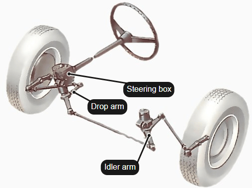


Rack And Pinion Steering System
The most common steering system, the rack and pinion gets its name from the two gears it uses, the rack (the linear gear) and the pinion (circular gear). This system is used in most of the cars and is usually not employed in heavy-duty vehicles. Its working may appear complex but uses quite simple physics.
Construction Of A Rack And Pinion
Rack and Pinion
The steering wheel has a shaft attached to it and on the other end of the shaft is the pinion. The pinion is positioned on top of the rack and moves when the steering wheel is moved. The end of the rack has something called a tie rod. The tie rods connect to the steering arm which in turn is connected to the wheel hub. Onwards to the working of rack and pinion.
Power Steering System
Power-assisted rack and pinion
The power steering adds some more parts to the rack and pinion system which makes it easier to use. Mainly the pump, pressure tubes, rotary control valve, fluid lines and a hydraulic piston.
The job of the pump is to as you might have guessed, pump the fluid around when needed. The rotary control valve ensures that the movement of fluid is only performed when the driver is actually steering the car. The hydraulic piston moves around depending on which fluid line brings the high-pressure fluid. This piston movement on the rack makes it easier for the driver as it is applying most of the force necessary to steer the car. This concludes the brief discussion on how a hydraulic power steering system works.-
https://gomechanic.in/blog/car-steering-system-explained/
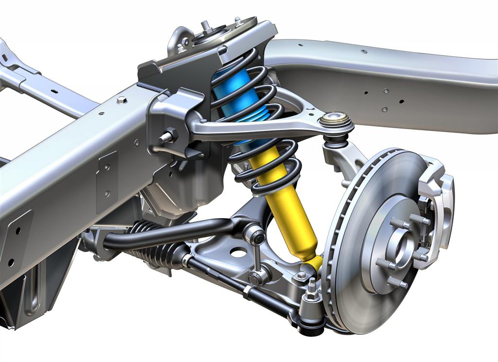
SUSPENSION SYSTEM
There are various ways of attaching the wheels of the car so that they can move up and down on their springs and dampers , and do so with as little change as possible in the distance between adjacent wheels or in the near-vertical angle of the tyres to the road.
The front wheels must be free to pivot on their steering swivels. The driven wheels, whether front or rear, must also be free to rotate with the drive shafts .
Non-independent suspension
A rear-wheel-drive car often has a live axle , a tube containing both the drive shafts (half shafts) and the differential gears . A four-wheel-drive car may have a live front axle as well.
A dead axle - a rigid beam - is now used at the front on vans and trucks only. Some front-wheel-drive cars have a dead rear axle.
A rigid axle will have springs and links to prevent sideways movement.
Independent suspension
Wishbone suspension
A double-wishbone suspension. Wishbones are fitted at their outer ends to the top and bottom of the steering swivel member. The two forks of each wishbone extend inward to pivot on the frame. A tie rod - a steadying bar - is connected between the frame and the lower wishbone.
Instead of sharing a common axle, each wheel on a car with independent suspension is independently attached to the body or subframe. Different spring combinations may be used.
When driven wheels are independently suspended, the differential is fixed to the frame and drives the wheels by jointed drive shafts.
There are five types of suspension system in common use.
Double wishbones are used mostly at the front. There are two wishbones, one above the other, to keep the wheel upright as it rises and falls.
MacPherson-strut suspension can be used at both front and rear. The wheel hub is fixed rigidly to an upright, telescopic, tubular strut which has its top end anchored to the frame or to a reinforced wing.
On front wheels, the whole strut swivels to allow steering. Pivoted arms extend inward and forward to the frame in order to keep the wheel upright and resist accelerating and braking forces .
A trailing arm is attached to the wheel hub at one end, and extends forward to a pivot on the frame.
The arm may be broadened into a V shape with two pivots, either side by side or with the inner pivot slightly behind the front one - a semi-trailing arm. Trailing arms are usually found at the rear only.
Trailing-arm suspension
A trailing-arm suspension on a rear-wheel-drive car. The arm is attached to the rear wheel hub and broadens into a V whose two arms extend forward to pivot on the frame. The differential is fixed to the frame and the drive shafts have universal joints.
A leading arm , used only at the front, is the opposite of a trailing arm, with the wheel in front of the pivot.
Swing axles may be at the front or rear. The system is like a beam axle cut in half and attached to pivots on the frame.
Usually the half-axle is broadened into a V with front and rear pivots to keep it from twisting.
Anti-roll bars
Anti-roll bar
Pivots allow the bar to twist, but to a limited degree so that rolling is controlled.
To restrain cars from rolling - leaning over on corners - an anti-roll bar is used, often at the front, sometimes at the back and sometimes at both front and back.
It is a torsion bar crossing the car through two pivots on opposite sides of the frame.
Outside the pivots the bar bends back and one end is attached to each wheel, usually through one or two flexible rubber bushes.
When one wheel moves up it pulls up one end of the bar and the other end pulls up the other wheel, keeping the car level.-https://www.howacarworks.com/basics/how-car-suspension-works